1972 RR - FUSE BOX
Moderator: Site Administrators
1972 RR - FUSE BOX
Looking for an exploded diagram or photo of the main fuse box. Specifically, looking to replace the (interior) wires going into fuse slots 16 & 18. I need to know how the wires connect into the box, how to get access to them and replace the wires.
-
72RoadRunnerGTX

- GTX (RS)
- Posts: 593
- Joined: Wed Dec 27, 2006 6:44 pm
- My Cars: 1972 Road Runner/GTX
1972 Satellite Sebring
1972 Satellite Sebring(big block parts car) - Location: Seattle, Washington
Re: 1972 RR - FUSE BOX
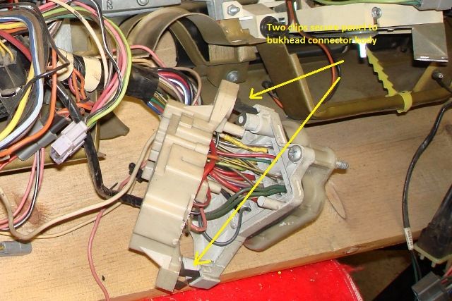
Basically, the fuse panel is clipped to the inside of the bulk head connector; it will come away and allow access to the rear of connections. Disconnect the wiring harnesses from the engine compartment side; the female “Packard” connectors have a locking tab holding them in place. Small extraction tool or screw driver inserted next to the connector will allow it to push back inside. The male connectors will remove when their sides are squeezed together slightly then pushed back out.
Removing the speed nuts securing the bulkhead connector to the firewall, pushing it back into the passenger compartment, will gain you better access to the connectors in the bulkhead connector.
Removing the speed nuts securing the bulkhead connector to the firewall, pushing it back into the passenger compartment, will gain you better access to the connectors in the bulkhead connector.
Re: 1972 RR - FUSE BOX
So you are saying the fuse box is all one piece? I see two big phillips head screws - do i unscrew those to get the fuse box loose, or are you talking about different ones?
-
72RoadRunnerGTX
- GTX (RS)
- Posts: 593
- Joined: Wed Dec 27, 2006 6:44 pm
- My Cars: 1972 Road Runner/GTX
1972 Satellite Sebring
1972 Satellite Sebring(big block parts car) - Location: Seattle, Washington
Re: 1972 RR - FUSE BOX
excellent. Thank yoU!
Re: 1972 RR - FUSE BOX
I have posted two photos.
In one of them, I am trying to figure out what the strange connector is called and where i can get a new one.
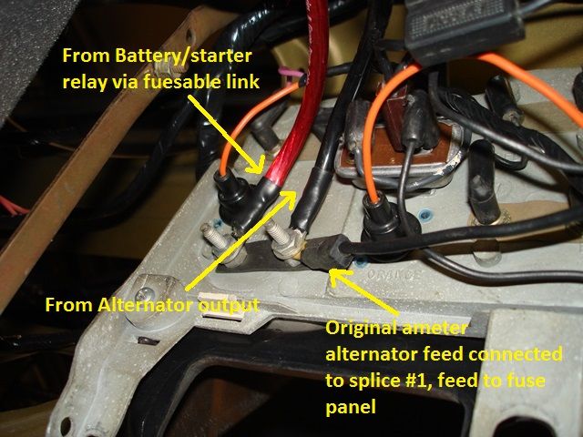
In the other one, i followed the black ammeter lead wire down and it was saudered into a crossroads of four other wires. Is this correct, or is this another rig job?
The red ammeter lead wire goes straight into the fuse box.
In one of them, I am trying to figure out what the strange connector is called and where i can get a new one.
In the other one, i followed the black ammeter lead wire down and it was saudered into a crossroads of four other wires. Is this correct, or is this another rig job?
The red ammeter lead wire goes straight into the fuse box.
- Attachments
-
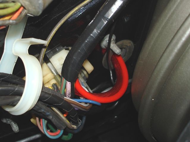
- The black ammeter lead wire was connected to this crossroads.
-
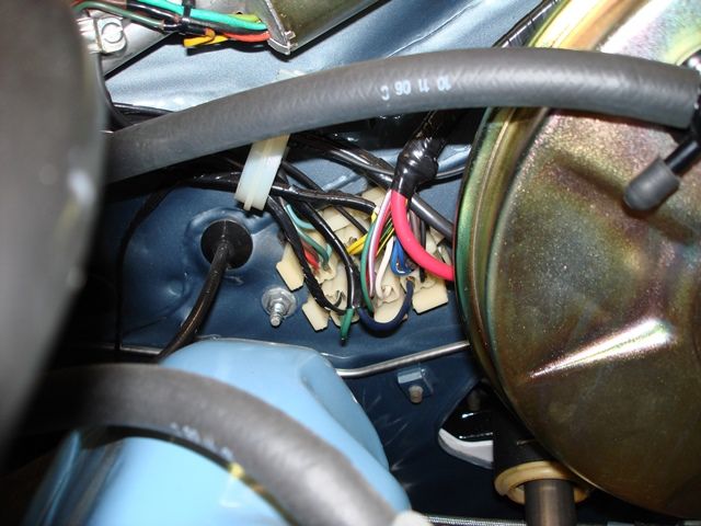
- This is where the hot wire from starter relay goes into back of fuse box.
-
72RoadRunnerGTX
- GTX (RS)
- Posts: 593
- Joined: Wed Dec 27, 2006 6:44 pm
- My Cars: 1972 Road Runner/GTX
1972 Satellite Sebring
1972 Satellite Sebring(big block parts car) - Location: Seattle, Washington
Re: 1972 RR - FUSE BOX
First picture is wire weld splice #1, diagramed on page 8-160 of the FSM, a copy of which I posted to your other thread; follow the diagramed black lead from the ammeter. It is factory and should be tapped up, then wrapped inside the harness loom. In the second picture, a classic example as to why it is highly recommended that the charging circuit bulkhead connectors should be by-passed altogether, running wires (preferably bigger wires)directly through the firewall to the ammeter and back.
Re: 1972 RR - FUSE BOX
The black ammeter wire went to the weld and then on to the fuse box where it continues to the alternator, correct?
Can you verify if i can do this: i want to tape the weld back up of just the four pictured wires, bypass the ammeter gauge all together and connect the black alternator wire to the red main power wire via a fusible link in the engine compartment without going through the fuse box at all.
Can you verify if i can do this: i want to tape the weld back up of just the four pictured wires, bypass the ammeter gauge all together and connect the black alternator wire to the red main power wire via a fusible link in the engine compartment without going through the fuse box at all.
-
72RoadRunnerGTX
- GTX (RS)
- Posts: 593
- Joined: Wed Dec 27, 2006 6:44 pm
- My Cars: 1972 Road Runner/GTX
1972 Satellite Sebring
1972 Satellite Sebring(big block parts car) - Location: Seattle, Washington
Re: 1972 RR - FUSE BOX
Just keep in mind splice #1 also acts as the main power feed to the entire car. If you by-pass the charging circuit completely within in the engine compartment, it will be necessary to provide the splice, or the under dash 12ga black wire, with power from the charging circuit. Do a search on modifying Mopar charging circuits, should find many detailed instructions on the internet as to how to go about it
Re: 1972 RR - FUSE BOX
Let's say i wanted to put in a voltmeter like you suggested before. I would simply hook up black and red to the voltmeter. My question is: does it hurt anything to run the black/red wires straight through the firewall, bypassing the fuse box? or does the juice need to run thru the fuse box?
-
72RoadRunnerGTX
- GTX (RS)
- Posts: 593
- Joined: Wed Dec 27, 2006 6:44 pm
- My Cars: 1972 Road Runner/GTX
1972 Satellite Sebring
1972 Satellite Sebring(big block parts car) - Location: Seattle, Washington
Re: 1972 RR - FUSE BOX
Not sure I suggested a voltmeter, others have advocated voltmeter conversions. If you go that route, no you can’t use the red & black ammeter leads directly to operate a volt meter. Volt meters need switched power and a ground. Biggest problem with ammeters original to these cars were loose connections at the ammeter (loose nuts) and poor/corroded connections through the bulkhead connectors, either leading to heat damage. I use the original undamaged ammeters with upgraded wiring and by-passing the bulkhead connectors. Routing wires through grommets in the firewall. As mentioned, still need to provide power to splice #1 via the original black ammeter lead.
Here's a link to some detailed information
Here's a link to some detailed information